ESP32-C3 · Wiring map
ST7735 160×128 · TTP223Signal · Hardware
WIRING MAP
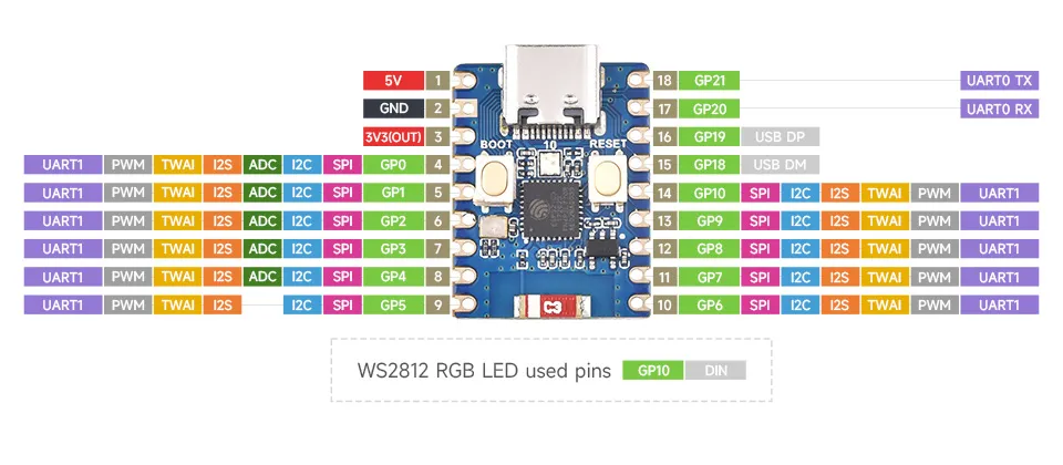
ESP32-C3-Zero (its WS2812 RGB LED is on the board) with the 1.8″ ST7735 SPI display and a TTP223 capacitive touch pad. This is the exact pin map the sketches compile against — TFT_SCLK 1, TFT_MOSI 2, TFT_DC 3, TFT_RST 4, TFT_CS 5, TOUCH_PIN 0, LED_PIN 10.
01 · Connections
The wires land on the pins in the photos. Click a wire — or a table row — to isolate it; filter by group.
| ESP32-C3-Zero | Module pin | Sketch define | Note |
|---|---|---|---|
| 3V3 | ST7735 · VCC | — | 3V3 rail |
| GND | ST7735 · GND | — | common ground |
| 3V3 | ST7735 · LED | — | backlight, always on |
| 3V3 | TTP223 · VCC | — | 2–5.5 V |
| GND | TTP223 · GND | — | common ground |
| GP1 | ST7735 · SCK | TFT_SCLK | SPI clock |
| GP2 | ST7735 · SDA | TFT_MOSI | SPI data out |
| GP3 | ST7735 · A0/DC | TFT_DC | data / command |
| GP4 | ST7735 · RESET | TFT_RST | display reset |
| GP5 | ST7735 · CS | TFT_CS | chip select |
| GP0 | TTP223 · SIG | TOUCH_PIN | tap / hold input |
02 · Reference
The board, with the used pins highlighted.
03 · Modules
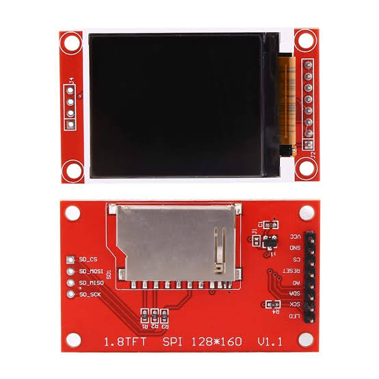
Pin names as printed on the boards in the photos.
- VCC→ 3V3
- GND→ GND
- LED→ 3V3 (backlight, always on)
- CS→ GP5 · TFT_CS
- RESET→ GP4 · TFT_RST
- A0 / DC→ GP3 · TFT_DC
- SDA→ GP2 · TFT_MOSI
- SCK→ GP1 · TFT_SCLK
- SDO / MISOnot connected
- SD_CS · SD_MOSI · SD_MISO · SD_SCKSD card unused
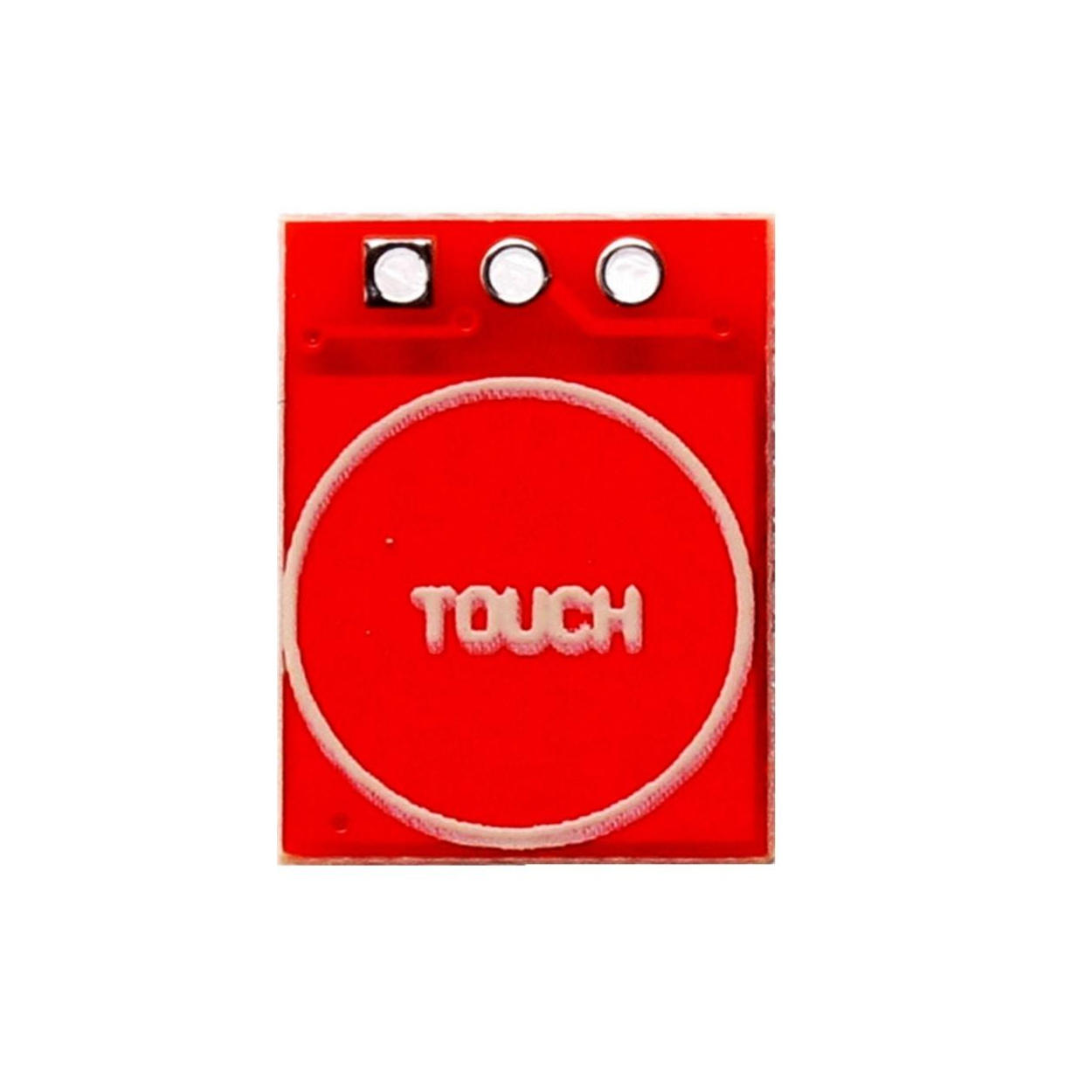
- VCC→ 3V3 (2–5.5 V)
- GND→ GND
- SIG→ GP0 · TOUCH_PIN